Daedalus Keyboard
Note: This is a trimmed down version of the full report. For a complete version refer to the GitHub Repository
Introduction
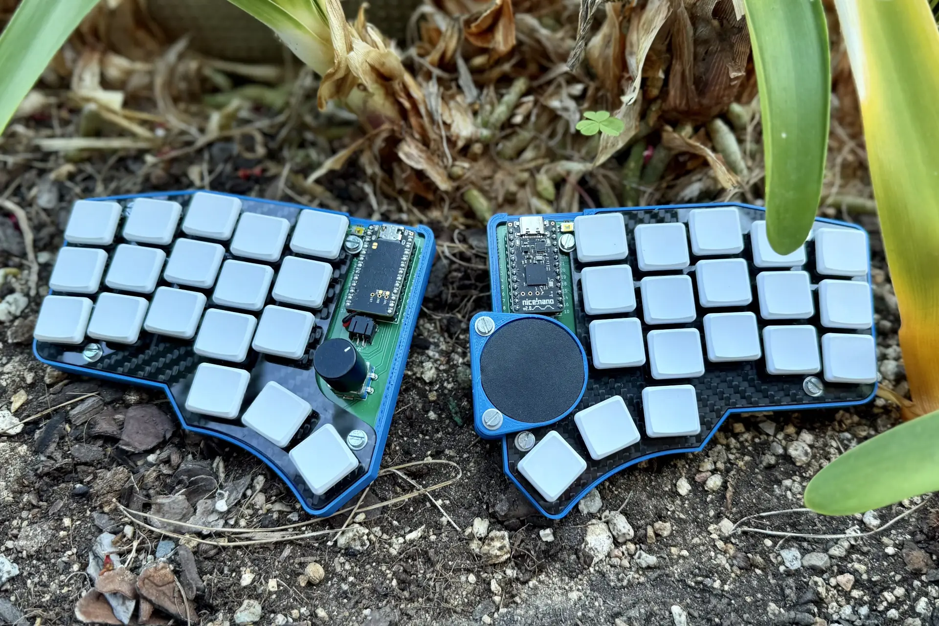
Daedalus is a split ergonomic mechanical keyboard that works wirelessly and includes a rotary encoder and a trackpad.
This document is intended to be the resource I wish I had when starting the project, and is therefore intended for users that wish to make their own keyboard or are interested in the technical details. It’s both a build log and a high-level guide and it includes tips along the way to help you with your journey.
All of the technical keyboard-related terms will be defined in the Nomenclature in case you may need it.
Throughout this document multiple resources will be listed and they will be referenced in the Resources section at the end. Even though they are formatted in a semi-academic manner, due to the nature of this project the listed resources may not be fit for academic purposes and they may be of varying quality.
Motivation
My motivations initially weren’t particularly interesting: After watching many videos on mechanical keyboards, specifically ergonomic ones, I had the consumerist itch to buy one, but I soon realized that ergonomic keyboards, namely the Corne, were very expensive. My first thought was to build one from a kit since that was cheaper, however I didn’t have any soldering skills. I heard that my university had a club where they could help you build stuff so I thought that they might be able to teach me how to solder the kit and I wouldn’t have to buy any equipment. Unfortunately, I was told that they were only able to provide help if you designed any of the parts, and since I didn’t want to design just the case, I thought I might as well design the whole thing. And that’s how it started.
Yet, as the project progressed so did my motivation, and my goal slowly shifted from wanting to use the end product to learning how to design and manufacture a working one.
Planning
Before starting the project, a plan needed to be made on what would need to be done and in which order. With the help of my mentor from the university’s Design Club we laid out a plan on what I would do and until when, and most importantly we set time constraints for each task with a Gantt Chart. It was one of the first Gantt Charts that I ever did, and it was the first project I did at this scale, so the estimates weren’t particularly accurate, but regardless it served as a guide on time management.
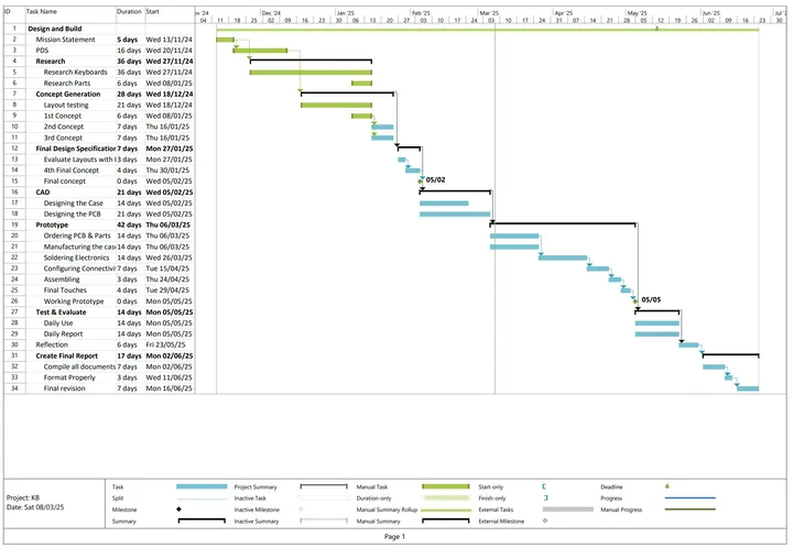 Fig 1. Gantt Chart of the project
As can be seen in the Fig 1, the project structure was going to be the following:
- Mission Statement
- Product Design Specification (PDS)
- Research (Keyboards and parts)
- Concept Generation (Layout Testing and sketching 3 concepts)
- Final PDS (Evaluate Layouts with Matrix and create final concept)
- CAD (Modeling the case and creating the PCB)
- Prototyping (Ordering, manufacturing and configuring)
- Testing
- Writing this documentation
In the end however, it looked somewhat different. I realized that the case had to be modelled around the PCB, not the other way around. Whilst ordering the PCB, I was designing the case/chassis and there was no time for testing. I also had to write the firmware at the time that the documentation was scheduled.
Product Design Specification (PDS)
Before starting a project like this one, you must first understand and constrain what you need. The characteristics and the properties of the project will be defined by your Product Design Specification (PDS). There are many ways of formatting but I categorized the properties by: MUST, Should or can. If I make a design that doesn’t include a characteristic from the MUST section it will not be valid, having one from Should will make it preferable than the rest, and the can category is completely optional.
It can also be a good idea to first list the parameters that you will take into account and split them into user and performance requirements. User requirements are about what the user needs from the product and it’s usually subjective, whereas the performance requirements outline the specifications that the product must have. I’ll admit, the difference is almost semantic, but distinguishing them may help.
For my context, as a university student, I wanted a comfortable keyboard that would be easy to carry around and place almost anywhere. Whilst using it I wanted it to have a small footprint, to not cause much clutter, and to not be distracting for others. I figured that to reduce the clutter I could embed the mouse into the keyboard, and that’s why I decided to also consider the input options into the PDS.
For the full PDS refer to the PDS at the Appendix. Note that the PDS was last edited at the starting stages of designing so even though the final product fulfills the requirements, they can be tightened up.
In a professional setting PDS are meant to stay mostly static, however, since this was a personal project and I was relatively new to it, I modified the PDS as I found the limitations of the hardware or as during research I found interesting qualities from other keyboards.
First-stage research
_Note: The full research can be downloaded or browsed at the project’s repository.
Keyboard Research
As described in the Motivation I already had some knowledge of keyboards and ergonomic keyboards, however during the research my goal was to expand my knowledge and exposure to many different types of keyboards to draw inspiration from. During my research I explored over 20 distinct keyboards made by the community and businesses that had features that I could extract for my keyboard. I compared the pros and the cons of each keyboard to evaluate them better, and I collected my thoughts on each of them. To visualize the keyboards better I used a moodboard as seen in Fig 4. It was during this research process that I realized that the keyboard that most closely resembled the ideal one for me was the Corne with some modifications: like the splay from the TOTEM,the thinness of the Ferris and the layout of the Chocofi.
At this stage, I found a tool called splitKbCompare to compare the layouts of various keyboards which allowed me to find similarities in them, as seen in Fig 2.
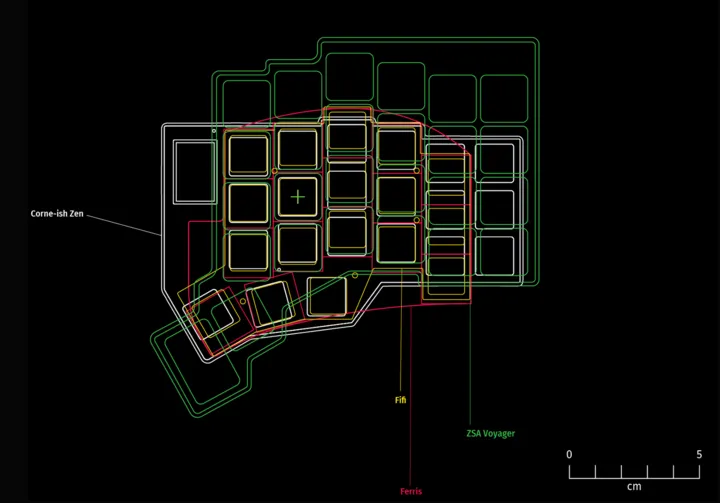 Fig 2. slipKbCompare screenshot
During the research process, thanks to my mentor I was able to get my hands on a Razer Tartarus (Fig. 3), the first ortholinear keyboard that I had ever used. Even though there were many things about it that I did not like, mainly because it wasn’t intended for typing, it provided very useful insight that would make me choose my keyboards better. I took into more consideration the build materials, the height of the keys, the actuation force, and the importance of having wrist rests. Being able to try out an ergonomic keyboard if you’re building one is definitely something that I would recommend, as you can only get so much information from reviews and images.
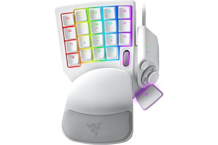 Fig 3. Razer Tartarus one handed gaming keyboard
Parts Research
Examining the keyboards from a broad angle made me have a clearer image in mind, but it is the components of the keyboard that make it. I researched all kinds of switches, luckily since I knew that I wanted low profile ones, it narrowed down the options quite a bit, but there were still many ones to choose from. I even considered using membrane switches, but discarded them after learning that they were hard to integrate and manufacture. Another interesting option that I considered to include in a future iteration of this keyboard were the ultra-low profile switches. They were fairly challenging to integrate, and weren’t as widely available as the regular ones, but the appeal of their thinness made me doubt for quite some time. In the end I didn’t go for them since I wanted to have something at least working in the first version. At this stage I didn’t have any clear candidates yet.
I also looked up alternative input options to the mouse, but I didn’t research them yet, that would be done later in the Second Stage Research.
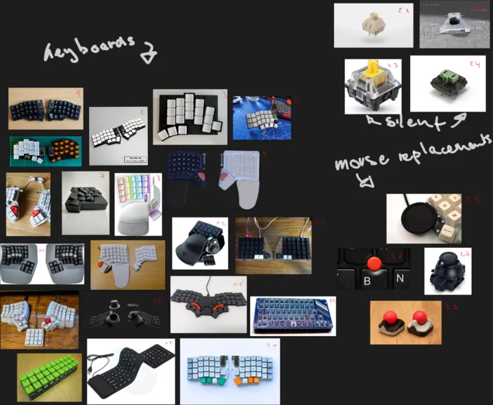 Fig 4. Moodboard of the different keyboards, switches and input options
Design Process
As seen in the Fig. 1, the design process overlapped with the research process, and it was at this time that I started experimenting with 1:1 scale sketches of the key layouts. By drawing where the comfortable resting positions and movement boundaries for each finger were and knowing the sizes of the keys I could create a layout tailor-made to myself. See Fig. 5 for reference.
It was in this first drawing that I also started experimenting with including other features to the keyboard, such as all the pointing devices that I knew of and even an overly complicated rotating mechanism of the thumb-cluster to save horizontal space 1.
 Fig 5. First sketch of the keyboard, drawn in 1:1 scale after my hand
Thankfully I was told by my mentor how to actually design the keyboard layout which was more or less as follows:
- Generate 3+ different isometric concepts (I made each of them focus on a part of the PDS)
- Score the concepts using a decision matrix with weights
- Create one final layout from the strong areas of each of them
Concept Generation
I was advised to do isometric drawings, and since I’m not a fan of drawing many not-so straight lines with rulers, I decided that I would draw it digitally. After some research I found out that it was relatively easy to do isometric drawings in Inkscape so I used that. I’ve always wanted to know how to make my own SVGs, and it was the perfect opportunity to learn about the most popular FOSS tool to make them.
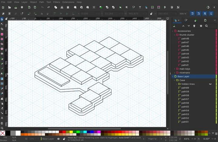 Fig 6. Inkscape editor of first concept drawing
The first concept that I made was rather simple since I was still learning how to use the SVG editor, but it had the core of the PDS, it was a Minimum Viable Product (MVP) of sorts, a baseline from which to iterate. See Fig. 6.
The next one that I made was maximalist of sorts. It was also double the thickness of the first since I was afraid that the previous one might snap in half. Similarly to the first sketch (Fig. 5), it featured many pointing devices and for maximalist sake, and 6 extra keys in the form of outer columns.
I think that at the third one I didn’t know what to do, so I just went with what would be the cheapest and simplest to build, or if you prefer a more fancy term: “minimalist”. I figured that to cheapen the cost it would be wired, as this would remove the need for a battery and for a microcontroller with BLE support.
The fourth and final one was just a render of the hand-drawn sketch (Fig. 5). Albeit I removed the thumbstick for a reason that I don’t know, probably for simplicity’s sake.
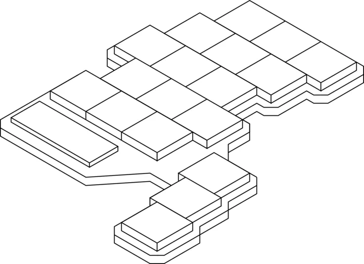 Fig 7. First concept, baseline
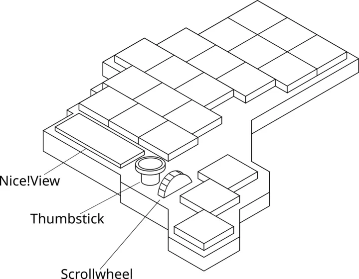 Fig 8. Second concept, maximalist
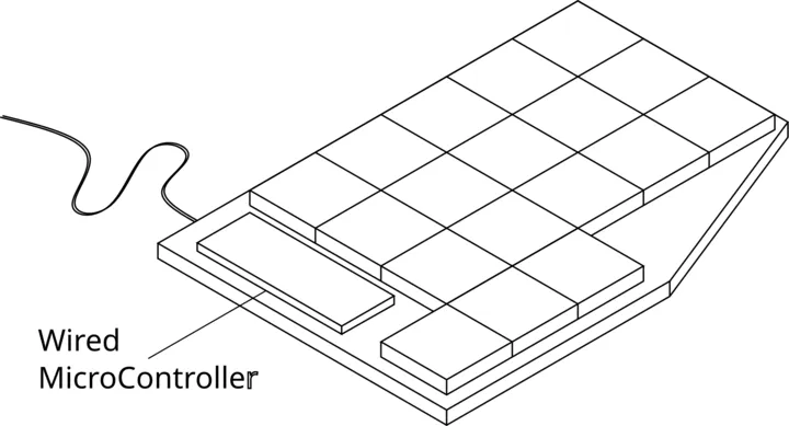 Fig 9. Third concept, minimalist
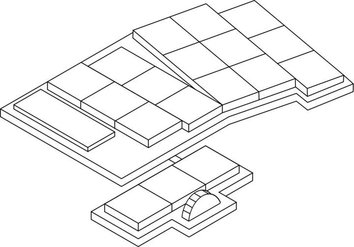 Fig 10.Fourth concept, sketch rendered
Decision Matrix
With all of the concepts done, the next step was rating them. There are many ways to do this, a weighted comparison is the best in my opinion. For each design, you score it in certain areas that were specified in the PDS, and depending on how much you value a certain area you give it a weight. The only hard part about doing this is deciding which weight you want to give to each parameter. Therefore it’s easy to fall into a confirmation bias, where you nudge the weights so that your favorite design wins anyways. There were many weights that I tried, and even different scoring techniques. One of them involved squaring the difference of the scores to 5 but keeping the sign. So that a 6 would become a 1 but, 9 would become a 16, and a 3 would become a -4. In the end, I didn’t end up applying it, but it might be useful in some contexts. What I did do, to end up with smaller, more manageable numbers, was subtracting the scores to 5 as I ranked positive scores above 5, and negative ones ranging from 1-4.
The areas scored were: Ergonomics, weight, size, aesthetics, durability, building ease, and input options. Given these parameters, the one that scored the highest was the maximalist, “Feature Rich” (Fig. 8). The full decision matrix can be found in the appendix.
Detailed Design
With that in mind I had a clear view of what were the best characteristics of each design, and so I set out to make a more detailed design that combined the best things for all of them.
It was at this stage that I realized that I couldn’t have a realistic design without having first the key layout set in stone. All the components of the keyboard, the size, and the shape revolved around it, since, what is a keyboard without keys?
Whilst looking at the Absolem Keyboard during the research, I found that the author made Ergogen a tool to define keyboard layouts declaratively using a simple YAML file. After reading through the docs, and by reverse engineering the given examples, I was able to define the layout that I had drawn on the paper (Fig. 5) into Ergogen. It took some iterations and some feedback from my mentor, but in the end it looked like what you can see in Fig. 11. Well, in the end I didn’t use the official ergogen, but rather the unofficial web deployment, maintained by Ceoloide since it had more features. You can find the full YAML configuration file in the project repository. Note that during development, the config file was expanded and the one showcased is the final version.
 Fig 11. Ergogen DXF output
With the key layout defined, I could look into the places where the components might go. Conveniently the output of ergogen can be exported as an SVG which means that I can edit it in Inkscape. Even though I named it “Final layout”, it wasn’t yet the final one as I would make more modifications later on, but it allowed me to see that there was space to place the microcontroller and the trackpad just above the thumb cluster. I also added it to the decision matrix and it won against the rest of the initial concepts, which I interpreted as progress. Regardless, there were some areas, such as the “Building Ease”, that I just guessed, and if I were to rate them now, I would probably give each of the designs different scores than they have now.
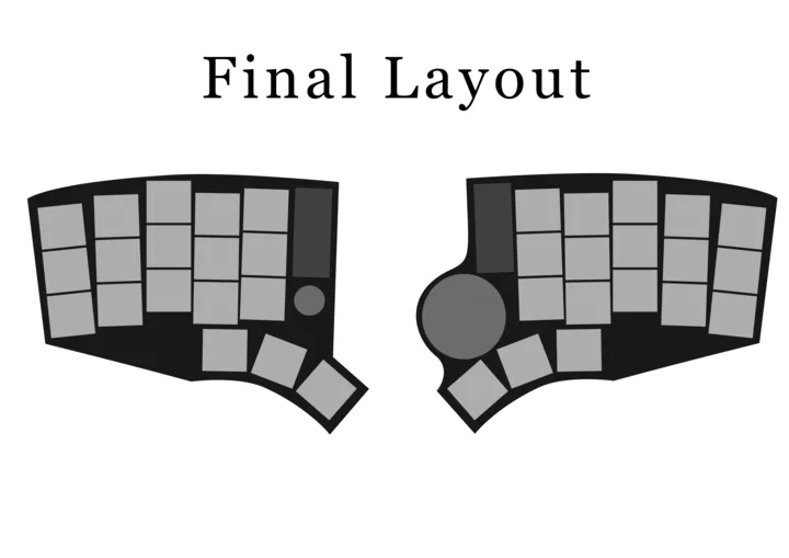 Fig 12. “Final” Layout
Second stage research
Now that I had a clear idea how the keyboard would look, it was time to research the specific components that I would use for each part. This part was quite extensive and there was a lot of notes and potentially useful information in it, however due to its length it doesn’t fit in this document, and therefore you will be able to find it in the project’s website. All of the products chosen in this section were the ones that were bought and used for the final keyboard.
Microcontroller
There are many options for microcontrollers, but since I wanted it to be wireless that narrowed it down quite a bit. Throughout the research I had encountered a lot of keyboards that used the Nice!Nano so I figured it must be reliable. Also, it used the well-known nRF52840 which almost all other wireless Microcontrollers used. Another thing that it had going for it was that it featured a total of 21 pins which was about as perfect for the keyboard that I wanted to build.
Interested in the microchip I decided to look at its product specification to estimate the power draw. Whilst reading the appropriate sections I familiarized myself with the different power states of the chip, which would be useful later on when I was working with the firmware. Through some rough calculations I estimated 24 days of battery life given an 80 mAh battery and 8 hours of computer usage per day of which (95% would be not typing any keys).
Conveniently (or not) soon after doing the estimates I stumbled across a power profiler by ZMK which confirmed my estimates 2.
Battery
Even though it was simple, it was quite hard to choose the exact model. It was clear from the start that it was going to be a Li-Po battery, but the problem I had was with the capacity and the manufacturer. I could go with a very big battery that could last me for days, but it would require a dedicated space for it, which would potentially elevate the keyboard; or I could go with a smaller one and fit it under the microcontroller, at the cost of battery life.
In the end I went for the 3.7V 301230 110mAh Li-Po battery that was sold at Typeractive.
Switches
I already looked at the options in Parts Research, but now I had clear which were the ones. It took listening to some switch sound comparison videos on youtube and some reviews on reddit, but after all I found the perfect switches for my use case: the LowproKB Choc Ambients Twilight. They are low profile, silent and designed by LowproKB the designers of the Sunset switches, one of the highest regarded low profile switches.
Trackpad
It was also at this stage into development that I had to narrow down on whether I wanted to use a trackpad, a thumbstick or a touchpoint as mouse replacements, but in the end I chose a trackpad for the following reasons: I’m already familiar with it, it’s very low profile and somewhat simple to integrate. Even though it occupies more surface area than the other options, I deem the reasons to be well worth it against the single disadvantage of size. Moreover, you can choose from different sizes and the one that I ended up choosing was just 35mm in diameter.
The brand in this case was very easy to decide upon since there was just one manufacturer that was ubiquitous amongst the ergonomic keyboards: Cirque. So the model that I ended up choosing was the Cirque Glidepoint 35mm 3.
Rotary Encoder
For the rotary encoder I went with a regular Alps C11 encoder since I had seen other people use it in the place of a key. Since more or less all the variants were the same I ended up going with the one sold at Mechboards.
Abandoned Parts
There were some parts that I didn’t include in the final design but that I had researched.
For some time I had considered including the Nice!View display but in the end I chose not to due to the price to value ratio.
I also considered adding a thumbstick and even bought one, but after seeing the mess that it would be to integrate with ZMK and having to write my own drivers, I decided not to. There were also some hardware limitations given that it was an analog device and I needed to work with digital current, so a converter should be bought.
PCB Design
After having chosen all* of the components and placing an order for them, it was time to design the PCB. For this I used the Ergogen tool to export the DXF file that I could import to KiCad, my PCB and Schematics editor. The unofficial fork supported defining different mounting holes, so I took advantage of that, and it can be seen in the last part in the ergogen config. I downloaded some of the parts from Joe Scotto’s and Ceoloide’s repositories. The Ceoloide’s was necessary for the elements that I described in the YAML configuration of the keyboard. With that I had a basic cutout of the PCB, the placement of the keys, and the mount holes in place.
Thanks to ergogen, it automatically placed the right diodes in the right places, so all that was left to do was routing to the microcontroller. But to do the routes, first the schematic needed to be specified in KiCad’s own schematic editor.
Looking back, the process is very simple, however to get started I first looked at some resources and guides to learn how to use KiCad. Joe Scotto made a great video on the basics of keyboard designing in KiCAD, but it was the guide by FlatFootFox that really helped me out.
The schematic was just drawing a grid-like pattern and extending it, and afterwards connecting it to the MCU. To be honest, keyboard designing is nothing much more than just routing. There aren’t really any “hard” parts that require you to think, other than maybe avoiding vias, which is totally optional. All you do is connect the dots. See the final schematic in Fig. 13.
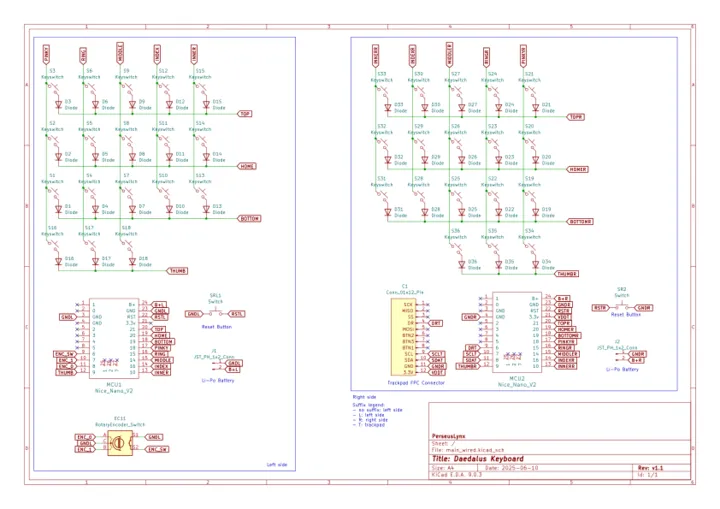 Fig 13. Schematic of the keyboard
The PCB was a bit more complex than the schematic but the principle is the same, just connect the lines (and this time you get told what to connect with what). Regardless, it took several iterations to get the PCB right, but it was well worth it in the end. I tried to apply all of the best practices I learned online and even sent it to some people for revision. Huge thanks to Zach and Bennytrouser for answering my questions and verifying my PCB, they helped get things like ground pour and proper spacing in the keyboard. The full PCB can be seen in Fig. 14.
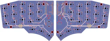 Fig 14. Final PCB design
Once the PCB was done it was sent for manufacturing at JLCPCB. In the meantime I was working on the chassis or the case of the keyboard.
Chassis Design
At my university I had access to CATIA so I used that. It’s probably overkill for what I ended up doing but it served pretty well. I had already started working on it whilst I was designing the PCB and also I used the university’s 3D printers to create some models to see how it would be.
After a bit of research on different keyboard mounting options, I decided on the sandwich mount because it seemed to offer the lowest profile, and the least building complexity. What you can see in the left diagram in is what I had in mind. With the bottom plate being acrylic (frosted preferably) to be able to see the PCB from below. Thanks to my mentor who pointed out that you can’t really fix a screw in a 1mm acrylic sheet and everything would fall apart. Unfortunately, I don’t have access to the previous CATIA renders, except for this one that I made whilst testing the “photo mode”, as seen in Fig. 15.
 Fig 15. Le Epic” titled render of an exploded view of an old version of the chassis
In the end I settled for the solution shown in the right of Fig. 16, which involves integrating some nuts into the chassis to hold them in place. Now I’ll admit, this is very sub-optimal, as with just the height of the nuts alone, the entire keyboard is elevated ~ 2.5 mm however, but it was the best working solution at the time. In the future, if I include surface mounted switches, the design could probably be improved and I believe that the height of the keys could be lowered substantially.
 Fig 16. Mounting Designs evolution
Trackpad holder design
The trackpad was tightly integrated with the chassis, so they weren’t two separate parts. I took inspiration from a community-made design intended for the Kyria, and made it a bit more compact since I could design the case around it. After some deliberation in the whiteboard (see Fig. 17) the final design was chosen.
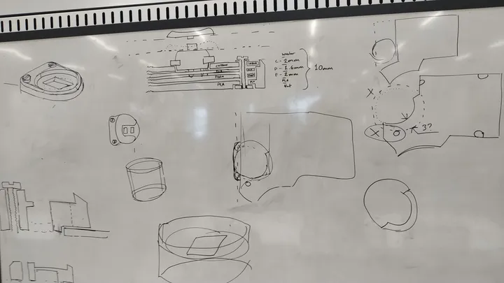 Fig 17. Trackpad Brainstorming in the whiteboard
Manufacturing and Assembly
Before the PCB arrived, all of the other parts had already arrived and the chassis was in its final form, so I started manufacturing the final parts. In the end the chassis consisted of layered parts: The 3D printed case, the sound dampening EVA foam, the PCB, and the carbon fiber top plate, all connected through a screw. It took a lot of time to design everything but putting it all together once done took less than 5 minutes.
During the last few weeks I made several prints at my university’s 3D printers (thanks!) and I could really start to see the design coming to life, and iterating on it. They would print overnight and the next day I would come back to see how they were and if there were any defects or things to improve. Due to the simple and vertical nature of the case, there weren’t many issues regarding the 3D printing methods, meaning I didn’t have to configure any support structures.
The trackpad holder 3D printed in the same way as the chassis, by tessellating the part, uploading the STL file to the 3D printer and waiting for some hours.
Before I had the PCB and the other components, I 3D printed them with the same dimensions to see if everything would fit inside the case, or if the switches would click into the top plate, as the tolerances were very tight there. Fortunately they did, and everything fit, as seen in Fig. 18.
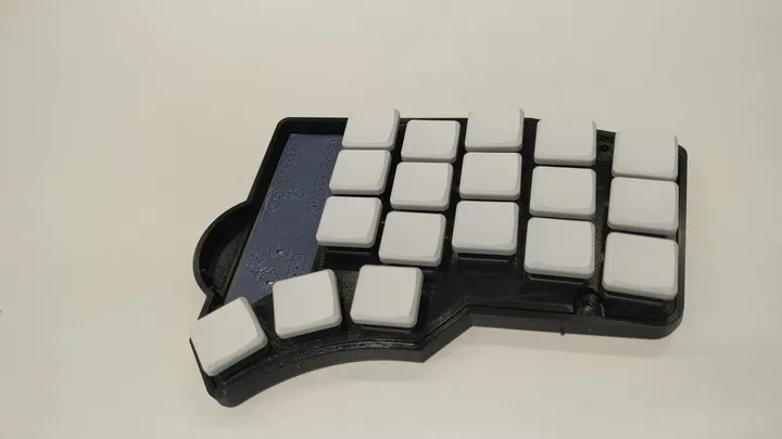 Fig 18. Testing Case print
Even though the most complex part, the chassis, had been 3D printed, the other easier-to-model parts such as the top carbon fiber plate and the foam couldn’t be 3D printed. For the carbon fiber plate I used a waterjet (although I couldn’t operate the machine) to cut a spare unclaimed piece of carbon fiber that was collecting dust in the university’s warehouse. (Thanks for letting me use it!). From the design in CATIA I made a DXF file to input it to the Computer Aided Manufacturing (CAM) waterjet machine as seen in Fig. 19.
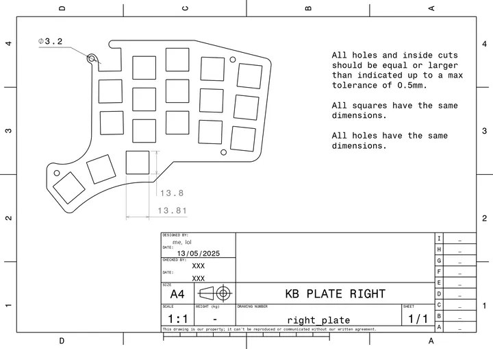 Fig 19. DXF Drawing of the right plate]
The foam on the other hand required a laser machine to cut precisely. After some research into different foams like Poron, polyethylene and EVA, I found that EVA was the easiest to buy, and it didn’t have any major risks when cutting it. Poron, on the other hand, released a variety of toxic fumes.
Cutting the EVA was very similar to the waterjet, in fact it required the same document to be made, a simple DXF file that I then uploaded to the software of the laser jets to specify where and how to cut.
Soldering
Soldering was very fun. It was the first time that I had done it in probably 10+ years, so it was like doing it for the first time. This meant that I had no idea about what I was doing, but I didn’t screw up bigtime thanks to the university staff that teached me how to solder properly. Turns out that soldering flux is great! Still, even under supervision, I managed to solder a nice!nano the other way around, which was annoying but it teached me how to unsolder. Well rather, the only thing that I learned about it is that it’s annoying, and it’s a good incentive to do things right the first time around. The very hard part though was with the trackpad…
So, it turns out that the part that I had specified in the PCB editor, and the part that I had bought were not the same… I don’t know how I didn’t notice that but it turns out that the 6 or so FPC connectors that I had bought were not compatible with the layout printed on the PCB, this complicated things a lot since it meant that the FPC cable had to be directly soldered into the traces. Luckily they were the same distance apart as the cable, but it was still very tricky. Well, it seemed like it was tricky because I didn’t do the soldering, but rather a member from the staff who was an expert at this kind of sub-milimiter soldering. If I had to do it alone, I would just order a new PCB, but since I was constrained by time, I couldn’t afford that, and with the staff being there it was the only solution. Therefore, now if you ever opened my right-hand keyboard you would find an FPC cable glued to the PCB with silicon. It’s not perfect but it does the job, and I couldn’t have ever done it myself, so thanks again to the amazing staff at my university. Unfortunately I didn’t make any pictures of it, so you’ll have to use your imagination.
However, there are some pictures mid soldering such as: Figs. 20 to 22.
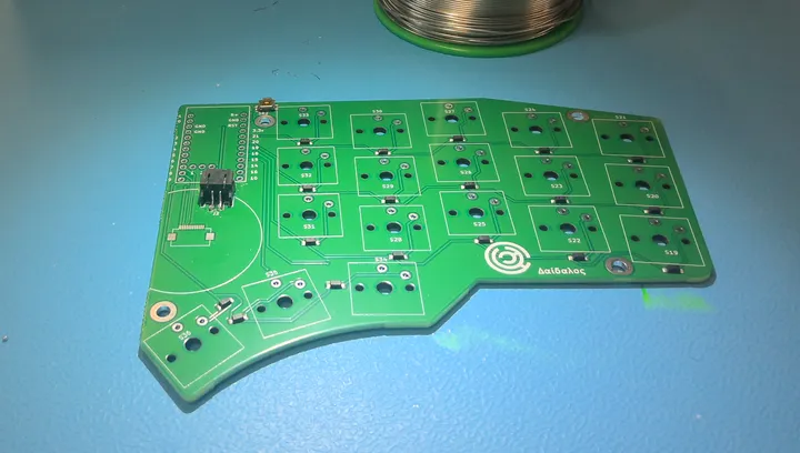 Fig 20. PCB with just the battery connector soldered
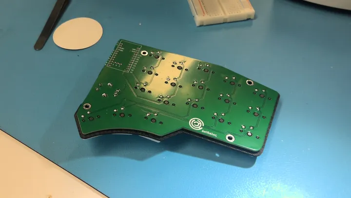 Fig 21. Backside of the PCB with all the switches soldered
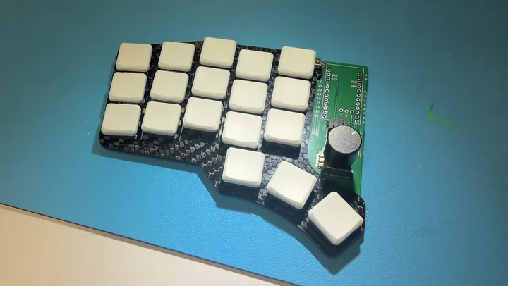 Fig 22. Keys soldered to the PCB with the carbon fiber plate in between]
Final touches
Once everything was soldered into place, I re-printed the chassis with a color of my liking, and once it was done printing, I screwed in the screws and that was it! In Fig. 23 you can see how it looked when assembled for the last time.
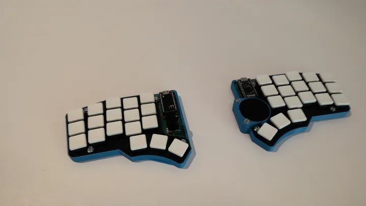 Fig 23. Final assembly of the keyboard
Afterwards (and with a better camera) I made some more pictures which you can find below, as well as a Gallery section at the Gallery.
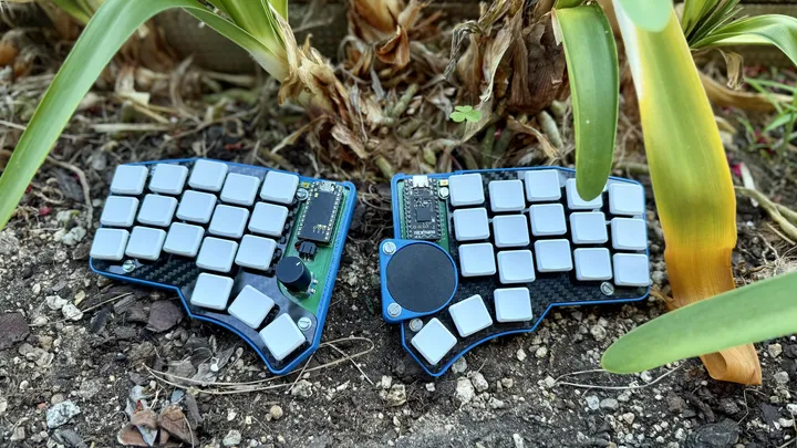 Fig 24. Daedalus in a plant pot
Firmware
The firmware that I ended up choosing was ZMK just because it was the de facto solution for wireless keyboards. ZMK has an amazing documentation, if you want to configure a pre-existing keyboard, however, when it comes to building your own, the steps were a bit more fuzzy, but it was still manageable.
You can find all of the code in the github repository of the keyboard at the github repository.
One of the biggest obstacles that I encountered was the CI build times from GitHub. Each time that I had to make a new version, github would almost always redownload everything, check all of the keyboards, and run the whole thing as if it were its first run, which made it take anywhere from 2-4 minutes per build depending on how major the error was. I think that you can specify GitHub actions to somehow cache data so that subsequent builds are faster, but after quite a lot of time spent researching, I couldn’t get it to work, so I just gave up on that. Another idea that I had was to run my own local toolchain, as in, I would do the compilation myself, but that was even more complicated somehow as I couldn’t get it to work either. I had spent hours trying alternative methods, and in the end I thought it might as well be easier to just wait between compilations.
Regardless of whether you are using GitHub CI or local toolchains, it’s extremely helpful to use git versioning properly. You can even use the GitHub Desktop for windows if you prefer a GUI, but I cannot stress enough how important version control is in software development. Sometimes you make large changes that break the code, and being able to revert back to the last stable version makes everything much easier. Other times, you just want to see the progress that you made in the code, and git also enables that. Though not necessary, I recommend using Conventional Commits naming convention or similar, as it will make traversing the git tree much easier.
As for writing ZMK firmware, the difficult part is understanding which code is required and in which file you need to place it. Sometimes the documentation is not very explicit with this, so it makes it a bit hard to guess which file they are referring to. I’m considering making a guide on how to create the ZMK firmware for your custom keyboard, but it would be too long to fit in this small document. If I end up publishing it, you will find it on my GitHub. Regardless, you can find below the tree of the project and a high-level overview of the use case for each file:
├── boards
│   └── shields
│       └── daedalus
│           ├── daedalus.conf
│           ├── daedalus.dtsi
│           ├── daedalus.keymap
│           ├── daedalus-layouts.dtsi
│           ├── daedalus_left.overlay
│           ├── daedalus_right.overlay
│           ├── daedalus.zmk.yml
│           ├── Kconfig.defconfig
│           └── Kconfig.shield
├── build.yaml
├── config
│   └── west.yml
└── zephyr
    └── module.yml
As you may notice, most of the files are inside boards/shields/daedalus, as that’s the configuration of the board. The other files are the configuration for the compiler, and they tell him the libraries to import and the structure of the code.
The .conf file tells the compiler which features the keyboard has, such as: deep sleep, encoders, bluetooth settings, etc. The .zmk.yml is like a manifest file with metadata, and it’s useful when importing this board as a module.
Both the Kconfig files don’t specify anything themselves, but rather help link files between them. The .overlay files are also helper files that in my case just specify which rows correspond to the pins in the MCU.
The two most important files are: daedalus.dtsi and daedalus.keymap. The former defines the key matrix, the pins for each column, the key behavior, and the trackpad and encoder. Whereas the latter defines the, well, keymap of the board.
90% of the time that I was working on the firmware was either reading the docs, reading my code to find the bug, interpreting error messages or waiting for builds to complete. If you want to create your own board, what I would recommend is: Skim through the docs at first, to familiarize yourself with ZMK, and then clone some working repository (like mine) and, with the help of the docs, try to reverse engineer and modify it to suit your needs. I think that’s the fastest, and less troublesome way to do it.
Lessons Learned
Don’t leave stuff for later !!!
Even though I worked every week on the project, I spent way longer than I should on the initial stages of research. Not because I was overwhelmed, but because I thought I’d have infinite time. The project duration was constrained by the start of the summer vacation, so it definitely wasn’t infinite. This meant that during the last 2 weeks I had to put in as much work as I did during the first few months of the project. As you can guess, this is not optimal, and meant that things were rushed, this was the root cause of the issues described in this section and the next future_development.
Model PCB footprints after items you CAN buy or have already bought
This was probably the biggest mistake in the project. There were 2 parts, the FPC connector and the reset buttons, that didn’t match the footprints, and this caused severe issues with the build quality.
As mentioned, the FPC cable had to be soldered directly to the PCB routes which made everything unnecessarily complicated and fragile.
As for the reset button, it meant that it was just connected by two points, which made the left side reset button bend and not work properly, which means that if I want to enter the bootloader mode and I don’t have my keybinds defined for it, I need to use nailclippers (yes, nailclippers) to double tap the VCC and the boot pins to start the bootloader.
There are more components than just the main parts
This also stemmed from the rushed final part of the project, but when I researched the components, I just researched the ones that were the most important ones without taking into account which filament I needed, which screws, or the FPC connector nor any of the buttons. This was also probably why I forgot to include a power off button. I should’ve taken into account all of the components and I should have made a comprehensive Bill Of Materials (BOM) from the start.
Don’t buy items that don’t provide a product specification sheet
Kind of related to the last point, but don’t buy sketchy stuff. If you want things to last, just avoid items without an SKU or from a random manufacturer.
In my case I needed to find a “turtle” button (horizontally activated but surface mounted) that matched the dimensions of the footprint I had already printed in the PCB I had already ordered. Unable to find any anywhere, I eventually found something promising on Amazon that claimed to have the size I needed (Fig. 26). To the surprise of no one but me, it didn’t fit. So lesson learned, buy from a reputable vendor that includes a product specification sheet.
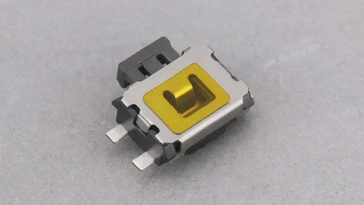 Fig 26. Turtle Switch I used
Future development
As you have seen,as you’ve followed through all of the process, there are plenty of things that could’ve been done better in the current design, some of them are fixes, and others are features that I’d like to add. But below is a comprehensive list of the projects I have planned for the keyboard:
Fixes
Maybe errors are to be expected from a version 1.0 (some would even call it 0.1), but regardless here are the fixes that I would apply to in v1.1:
- Add a connection from the DR pin to the MCU for the trackpad to work properly(fixed in PCB editor)
- Change the FPC Connector footprint to an FPC connector that I can buy
- Change the reset button footprint to a button that I can buy
Improvements
- Change the carbon fiber plate design to cover more of the board
- Use resin instead of filament for a higher quality chassis
- Reduce the key padding to make the keys closer together
- Figure out how to run a local toolchain
- Reduce the key spacing
New Features
- Add a power-off button! It would really improve the battery life.
- Add a protector case for the microcontroller to improve longevity
- Change the Choc switches for ultra low profile, solder mounted switches. This would require changing the whole chassis (v2?)
Credits
Even though it’s a project that I started on my own, it couldn’t have been possible without the help from wonderful people and amazing organizations.
I’d like to especially thank my mentor Bear, staff of the Design Club, who helped me throughout all my journey from the design to the last part of manufacturing, and who provided invaluable feedback and guidance all throughout and even stayed some extra time after his shift.
Thanks to my university, for having the amazing Design Club and for allocating the necessary resources and more into it, such as all of the equipment that I got to use, the software, and all of the supporting staff from the Electronics department that made soldering this mess somehow possible.
Without the RS Student Fund this project couldn’t have ever been financially viable, so I’d like to thank them for believing in me, and funding my project which fully covered the costs of manufacture.
Thanks to all the other amazing people that helped this project become what it is now: Zach and the Absolem and ZMK Discord members for providing valuable feedback in their areas of expertise, and to my friends and family for supporting me throughout this journey.
Gallery
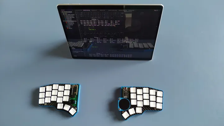 Fig 27. Completed daedalus in use, whilst editing it’s own firmware
 Fig 28. Right side close up
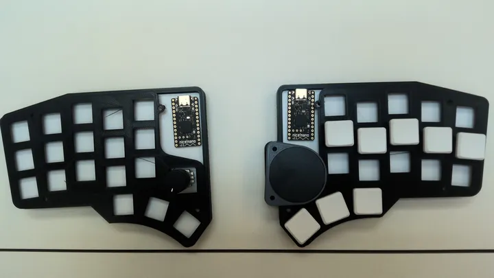 Fig 29. Partial assembly of the keyboard before assembly, because I wanted to see how it would look
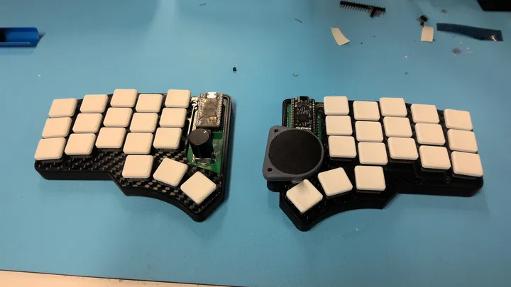 Fig 30. Deadalus just after finished soldering and fitted inside the temporary casing
Appendix
Product Design Specification (PDS)
User Requirements
- Ergonomics
- Weight
- Portability
- Aesthetics
- Durability
- Ease of manufacturing
- Input options
Performance Requirements
- HID Compatibility
- Latency
- Key rollover
- Battery life
- Recharge time
- Noise
- Connectivity
MUST
- MUST be able to send input to a computer (HID Compatibility)
- MUST be comfortable for me to use (ergonomic) for extended periods of time
- MUST have two physically disconnected parts
- MUST have symmetrical key distribution on both sides
- MUST have between 30 to 50 keys in total
- MUST have < 100 ms latency
- MUST be ZMK/QMK/VIA compatible
- MUST weigh < 600 g (less than a Nuphy Air V2)
- MUST fit inside a compartment of my backpack (25 x 8 x 35 cm)
- MUST be quieter than 50 dB (key presses)
- MUST have < 70g switch actuation force
Should
- Should be compatible with Khail Choc Switches
- Should have < 50 ms latency
- Should have a structural support layer attached to the PCB. (i.e. improves rigidity, strength etc.)
- Should weigh < 300 g (between Corne and Lily58 weight)
- Should support hot swappable switches
- Should support at least 8-key rollover
- Should have around 45g switch actuation force
- Should be wireless
- If wireless, it should have a battery life of > 7 days
- Should recharge from 0-100% in < 8 hours (one night)
Can
- Can have tenting
- Can have additional controllers (scroll wheel, trackball, etc.)
- Can have < 10 ms latency
- Can have a case
- Can have a carbon fiber plate
- Can have south-facing backlighting
- Can be connected, both pieces, with a magnet
- Can have a nice!view or similar
Decision Matrix
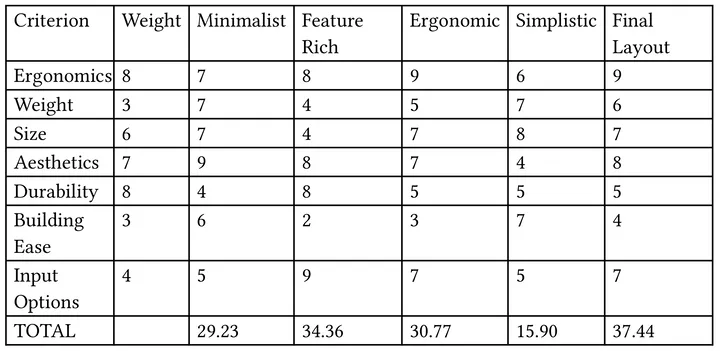 Fig 31. Decision Matrix
-
Even though I didn’t mention it in my notes, I think it was influenced by the Crosses Keyboard. ↩
-
In the end the estimates would not be realistic, since I didn’t incorporate any power-off button, so the keyboard would be on (albeit in deep sleep) all day long ↩
-
Initially I bought the trackpad without an overlay, so I had to buy it again, since I couldn’t easily print an overlay of my own. ↩